Generally fibre networks allow you to plug and play with fibre patch leads fresh out of the packet, and this is all thanks to some documentation that goes by the name, “TIA/EIA-568-B.1-7-2006 (Commercial Building Telecommunications Cabling Standard)”. It sounds like a thrilling read, I know, but in all honesty it is the most useful document avaialble when it comes to maintaining the polarity of multi-fibre connections, which most networks are based on. This standard includes advice on how to ensure polarity is switched and maintained over an entire fibre optic link, so when you plug in devices at each end, the transmitting and receiving diodes within the optics, whether fixed or modular, align correctly.
But there are occasional instances where you might wish to directly plug devices into each other without all the fixed infrastructure in between. For example, bench testing devices, or possibly even single links between two locations that use a pre-terminated cable, or even just an extremely long patch lead (they exist – https://www.amazon.com/Meter-Multimode-Duplex-Fiber-Optic/dp/B00551BQDE?th=1 !!!)
In these instances you may find you need to swap the polarity of the connectors at one end of your cable to ensure transmitters and receivers align correctly (TX/RX and RX/TX). This was easy with older connectors such as FC and ST as the connectors were simplex and physically unconnected to each other. You could quite literally ‘swap’ them over. But most modern networks now use duplex LC connectors, thanks to the standardisation of the connector on pluggable modules. So here is a quick guide to crossing the polarity of these leads.
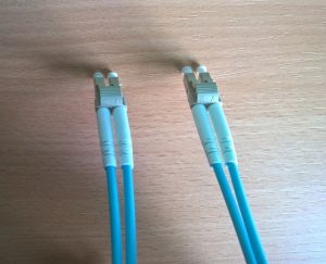
We will first presume you have a patch lead fresh out of the packet and the ends are standard A to A and B to B. This is normally noted on the release tab covers the clips on both sides of the connector.
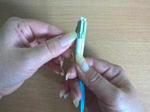
You first need to understand the construction of these connectors to disassemble them. Simply a duplex LC connector is two square simplex connectors joined together with a clip. Identify the opening on the side of the clip and prise it apart with a fingernail. Don’t afraid, these connectors are surprisingly robust and require some force to separate.
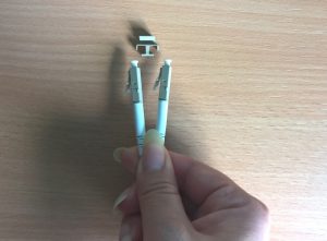
Once removed, repeat for the other side, noting which way round they were originally installed.
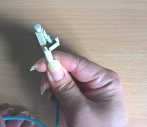
Then simply re-insert the connectors into the clip, in the opposite way round. It helps to angle the connector into the gap and then press into place. Again, don’t be too worried about applying some force here. Make sure the tab that goes over the release clips of the connector is the right way – covering the clips, so when you press down on the tab it disengages the clips on both sides of the connector.
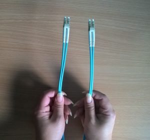
Complete! You now have what is effectively a fibre cross-over lead, remember to mark it so you don’t forget and save yourself some hours of troubleshooting in future.
